
The first jet propulsion engine patents were filed in the 30’s by the Sir Frank Whittle (English), in 1930, for his prototype schematics, while Hans von Ohain’s (German), in 1936, obtained a patent for his prototype. Both patents were remarkably similar, differing only in the internal arrangements. The first flights happened in 1939 for von Ohain’s jet and in 1941 for Whittle’s [1].
The developments proceeded during WWII, but a few jet planes became operational, like the Messerschmitt ME-262.
After WWII, the jet propulsion systems evolved at haste pace, with similar configurations but presenting much higher efficiencies, thrust and safety.
During the 80’s the Tokyo Shibaura Electric Co. (Toshiba Co.) patented a bladeless fan [2], shown in figure 1, which was later improved and patented by the Dyson Technology Limited [3] that commercializes the product worldwide.
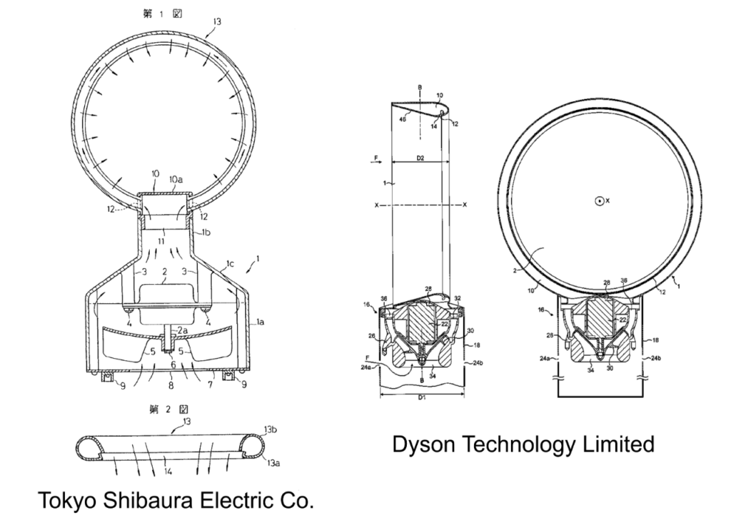
Figure 1 – Bladeless fans
Both fans operation is based on the Coanda Effect, that occurs when a fluid flows over a curved surface following its curvature. This is the effect that occurs on the upper side of a plane’s wing producing its lift, and therefore allowing the flight of a heavier than air device.
The association between the Coanda effect and air’s viscous characteristics allows a high-speed stream of air, traveling over a curved surface, to induce movement in the neighbor layers of air. This effect was dubbed by Dyson as “air amplification”.
When I first saw a Dyson fan in operation, the idea to use the same principle for jet propulsion struck me, but reaching a reasonable configuration took me a few years.
The configuration, illustrated in figure 2, named Hybrid Axial Jet Propulsion Device (HAJPD), is like a standard jet engine but lacks a physical axis, which is replaced by an internal free duct (4), which practically eliminates the risks of ingesting foreign objects. It also includes a ring-shaped radial centrifuge compressor (5) electrically driven (7), which aspirates a lean mixture of hot exhaust gases (2a) and pure air from the internal free duct (4) and injects it in the combustion chambers (6), where fuel is added and ignited. The combustion chambers are located near the air intake (1) allowing the injection of hot exhaust gases in the entrance of the internal free duct (4) to induce “air amplification”. This configuration reduces considerably the temperature of the gases circulating inside the internal free duct (4) and therefore the turbine (8) operational temperature, in contrast with conventional engines that require high temperature alloys and forced air cooling [4], as shown in figure 3, to avoid turbine blade melting.
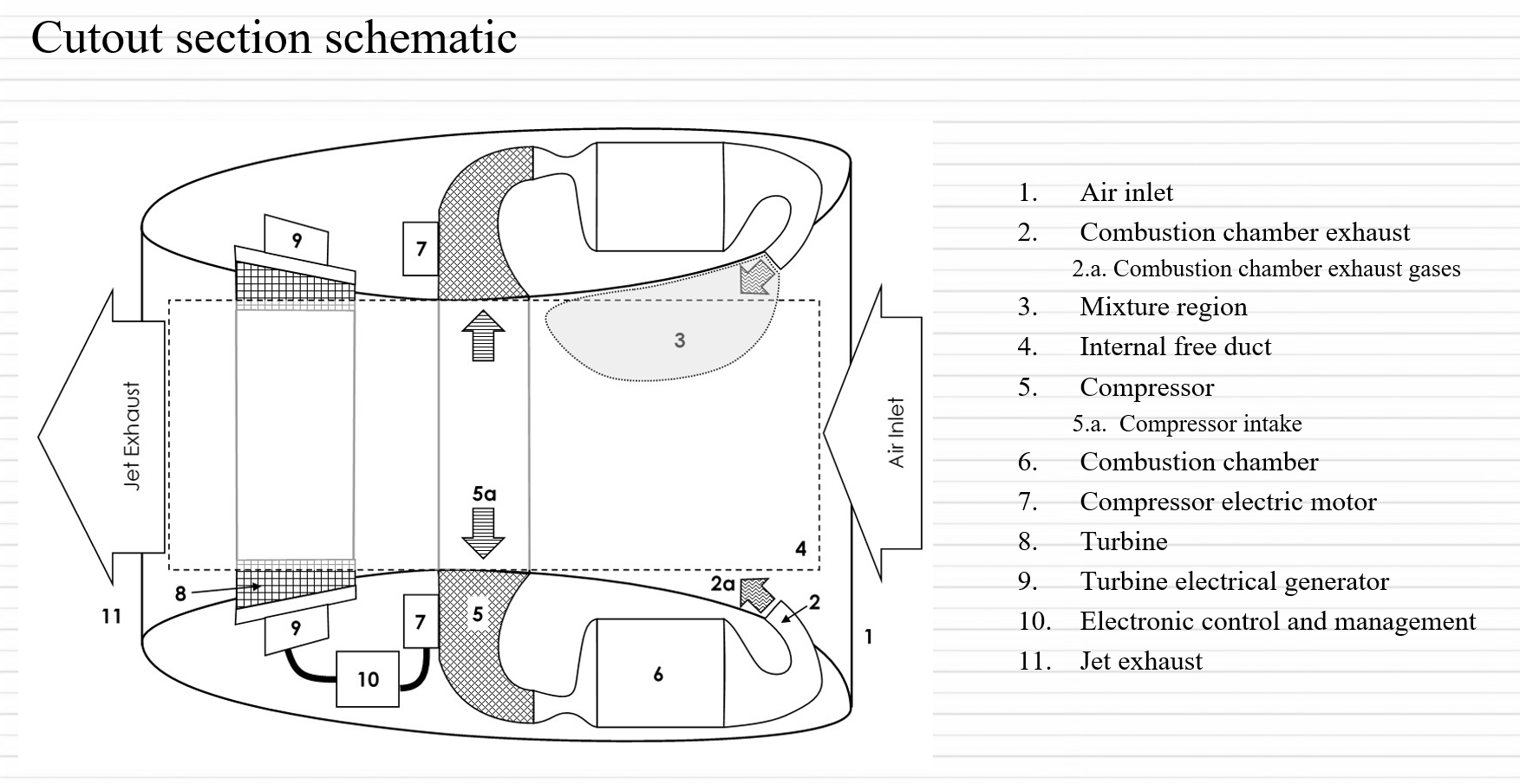
Figure 2 – HAJPD Cutout section schematic
Figure 3 – Hollow turbine blade for forced air cooling injection.
The turbine (8) is located after the compressor inlet (5a) and converts part of the kinetic energy from the gases circulating inside the internal free duct (4) into electricity (9) to feed the compressor (5) electric motor (7) and the remaining avionic systems.
Finally, figure 4 shows an artistic image of the HAJPD.

Figure 4 – HAJPD Frontal view evidencing the internal free duct (4), the compressor inlet (5a), colored blue, and the turbine (8) colored red.
Video
Video II
References
[1] – https://www.thoughtco.com/history-of-the-jet-engine-4067905
[2] – H. Shigeru and O. Masumi, Fan, JPS56167897A, priority from 1980-05-28
[3] – P. D. Gammack, F. Nicolas, K.J. Simmonds, A fan, GB2452593A, priority from 2007-09-04
[4] – F. Ahmad, M. Dankert, Hollow turbine blade, US7845905B2, priority from 2005-08-26